7 Way Trailer Plug Wiring Colors
The colors for a 4-pin trailer wiring diagram are: White: Ground wire Brown: Tail/running lights Yellow: Left turn/brake light Green: Right turn/brake light 18-gauge wire is the minimum recommended size for the 4-way plug. This should be used for the lights. With the ground wire, you want to use a minimum of 16-gauge. 4-pin Trailer Wiring Diagram

Trailer Pigtail 7 Way Wiring Diagrams Pdf Printable Floyd Wired
Above we have describes the main types of trailer wiring diagrams. Below is the generic schematic of how the wiring goes. 4 pin trailer wiring diagram. This type of connector is normally found on UTVs, ATVs and trailers that do not have their own braking system. Note, that this type of 4-pin connector is less common, that 4-pin flat connector.
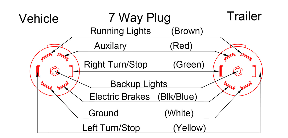
7 Pole Trailer Wiring Diagram Vehicle
Trailer Diagram. See the diagram below to understand better how 4-way flat harnesses are used.. (Original Equipment Manufacturer) sockets to provide a standard trailer wiring connector. Visually locate the socket and inspect the connection type to discover which type of trailer wiring harness you need, which can be determined by looking at.
7 Round Trailer Plug Wiring
Four-way wiring connection. Five-way wiring connection. Six-way wiring connection. If you find that you have one of these non-standard connectors on your vehicle or trailer but also a 7 pin connector on the other end, you'll need to do one of two things: Use an adapter that can sync the two different types of connectors, which is the easiest.

7 Way Trailer Connector Wiring
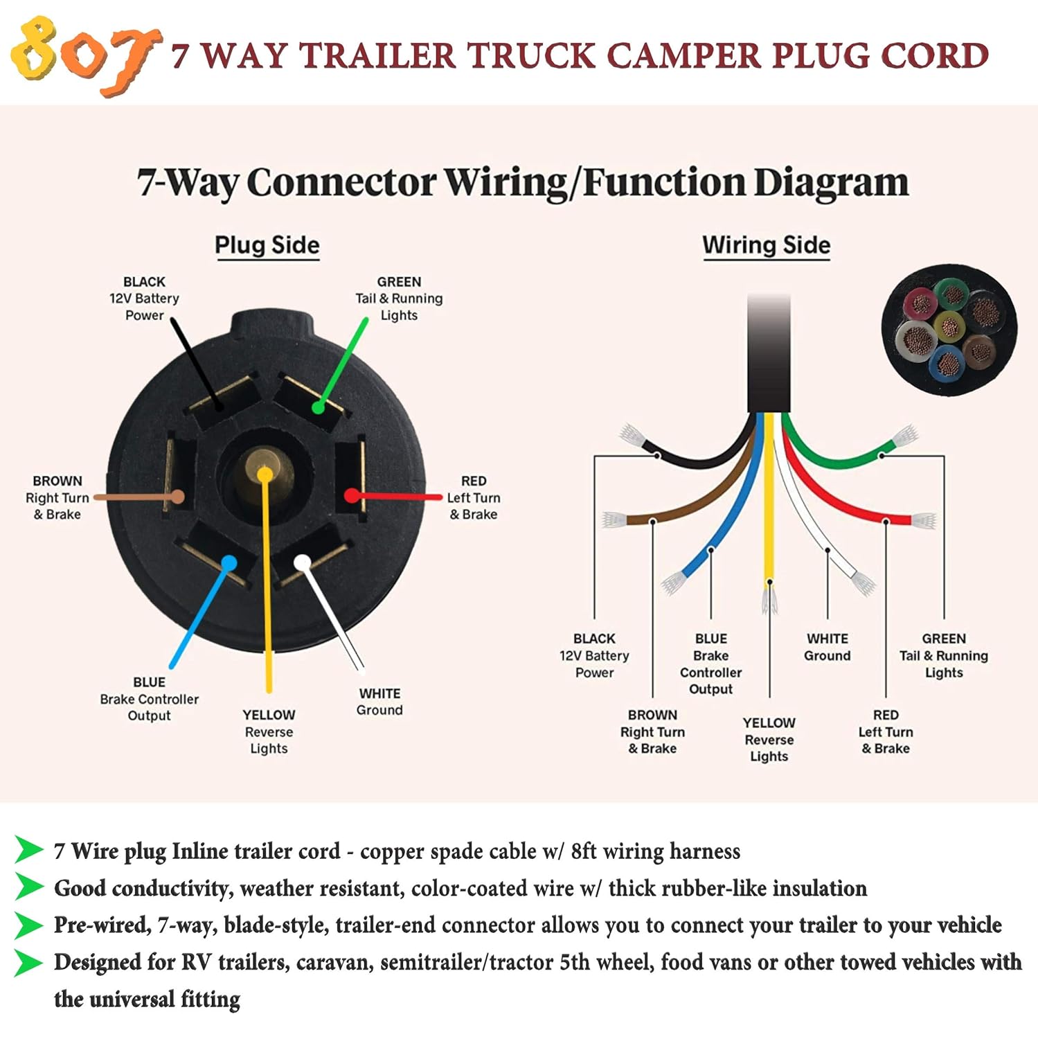
The 7-Way Trailer Plug is around 2″ diameter connector that allows an additional pin for an auxiliary 12-volt power or backup lights. It is usually used for towing heavy-duty cargo trailers, aluminum trailers, dump trailers, utility / landscape trailers, equipment trailers, open car haulers and enclosed car haulers.
7 Blade Trailer Connector Wiring Diagram Cadician's Blog
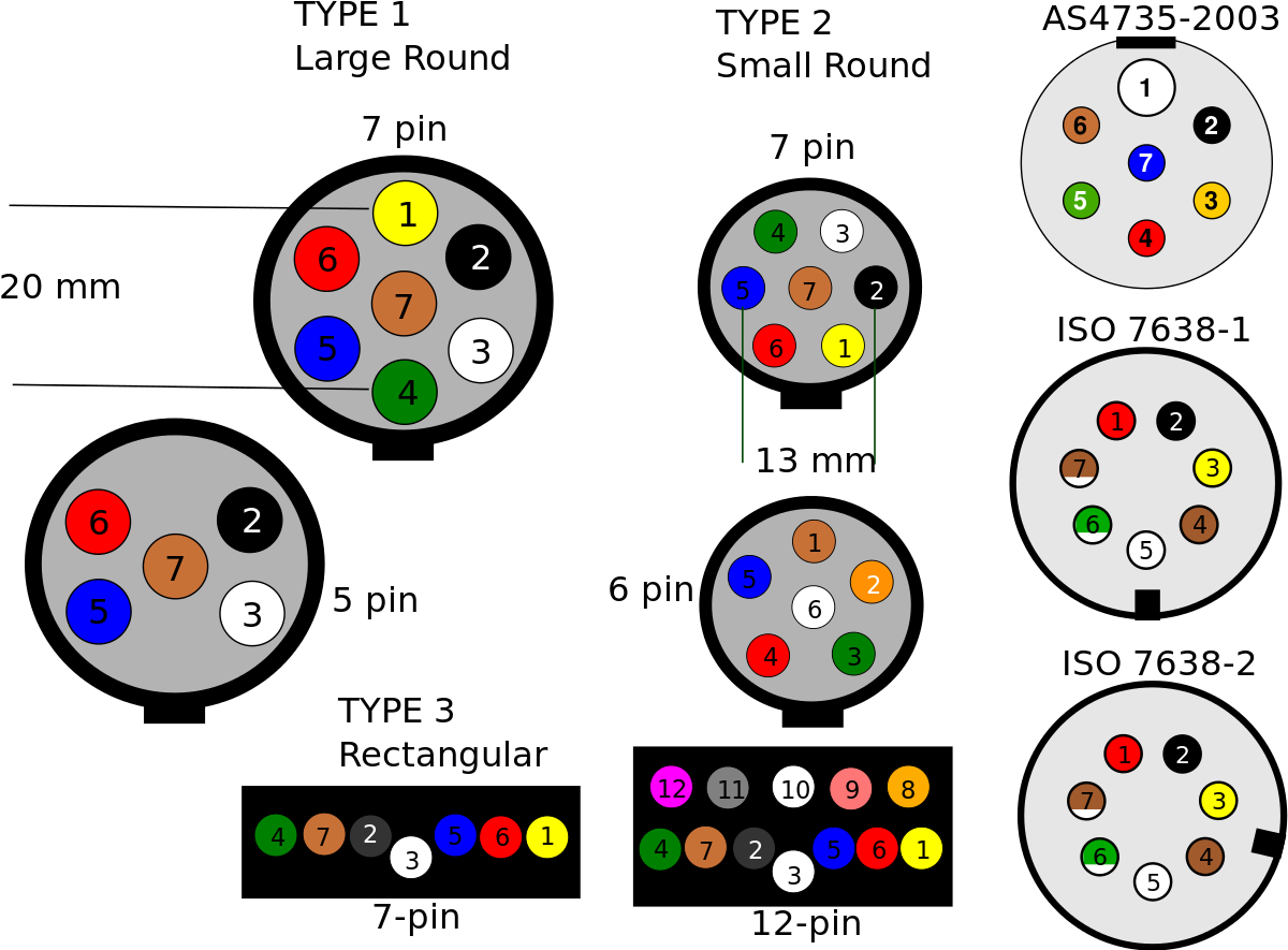
Australian Trailer Plug and Socket Wiring Diagrams 7 Pin Flat The best! All diagrams are as viewed from the Cable Side 12 Pin Flat This is an extension of the 7 pin flat. The 7 pin flat plug will fit into a 12 pin flat socket and work perfectly. All diagrams are as viewed from the Cable Side Small 7 Pin Round (QLD)
Wiring Diagram 7 Pin Trailer Connector
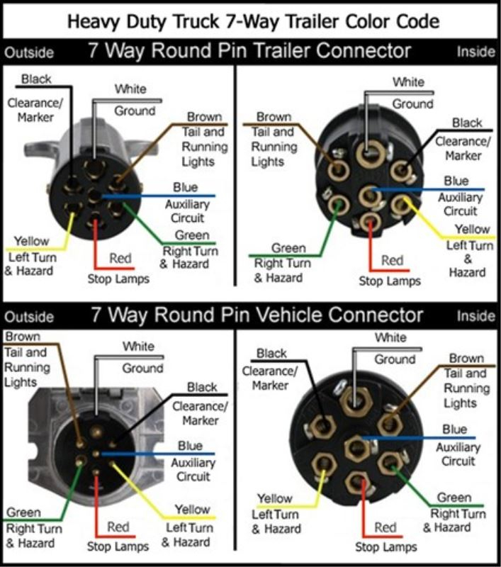
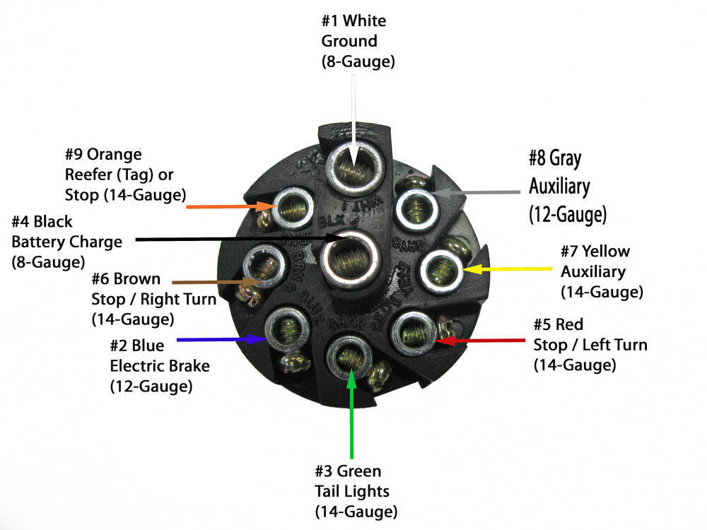
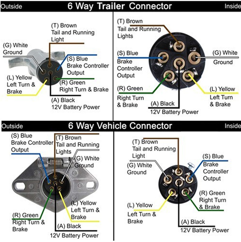
Standard Electrical Connector Wiring Diagram. NOTE: Standard wiring pictured below, viewed from the rear of connector (where wires attach). Not all trailers/vehicles are wired to this standard. The use of an electrical circuit tester is recommended to ensure proper match of vehicle's wiring to the trailer's wiring. On the 6 way plugs the.

Trailer Electrical Connectors Diagram
4 Pin Trailer Wiring Diagram 5 Pin Trailer Wiring The 5-pin trailer wiring is not as common as the 4-pin but its fifth function is very important. Typically the fifth wire added is a blue wire, which with the use of a 5-Way Flat will show the reverse or backup lights.
7 pole trailer plug wiring
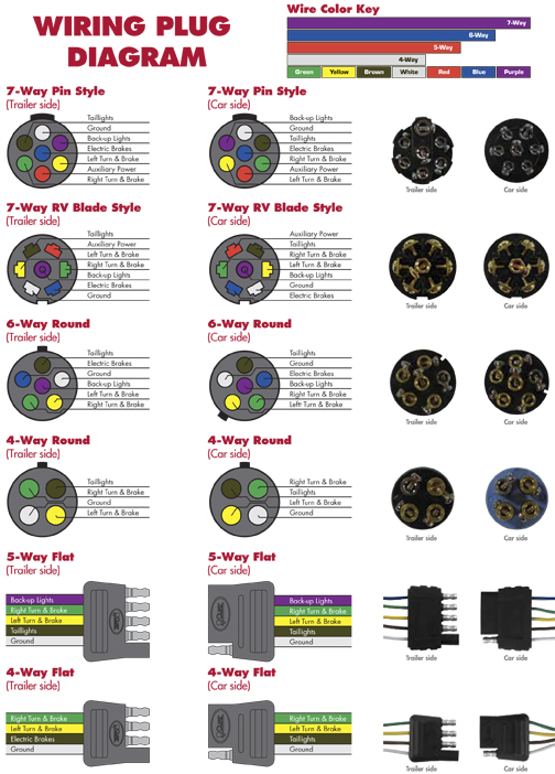
The images below show the Common Wiring Guide for Trailer Plugs, Adapters & Sockets. • Illustrations shown represent rear views of connectors. • The photos are what the adapters look like when removed from their housings. • The color key is a breakdown of the wires found in each of their respective systems. Note: The colors illustrated.
6 Plug Trailer Wiring Diagram
6 Way System, Rectangle Plug. 3/4 inch by 1 inch 6 way rectangle connectors right turn signal (green), left turn signal (yellow), taillight (brown), ground (white). The red and blue wire can be used for brake control or auxiliary. Use on a small motorcycle trailer, snowmobile trailer or utility trailer. Can also be used as custom wiring on.
6 Pin Wiring Diagram For Trailer
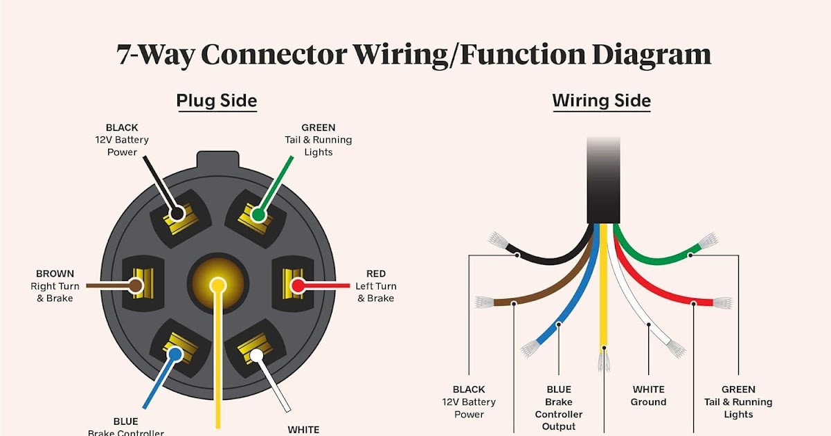
RV Standard Green: Tail/running lights Yellow: Reverse Lights Brown: Right turn/brake light White: Ground wire Blue: Brake controller output Black: Battery hot lead Red: Left turn/brake light Not sure exactly what each wire does? The easiest way to figure it out is to use a circuit tester to confirm the function of each wire.

Wiring Diagram For A Trailer Connector
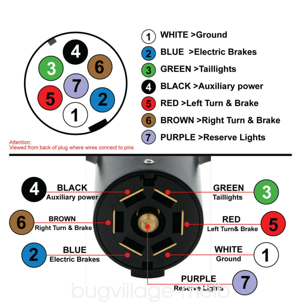
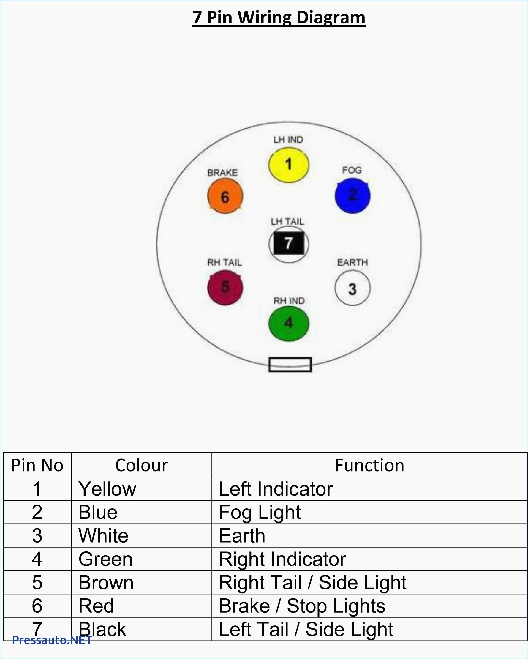
1 . White = Ground (See White Wire Notes below.) 2 . Brown = Tail Lights, Side Markers and Running Lights (See Brown Wire Notes below.) 3 . Yellow = Left Turn Signal & Left Brake Light 4 . Green = Right Turn Signal & Right Brake Light Please see the Trailer Wiring Diagram and Connector Application Chart below.
Tips for Installing 4Pin Trailer Wiring AxleAddict
03 Trailer Wiring Diagram [4-Pin, 5-Pin, 6-Pin, 7-Pin] 04 Use EdrawMax for Wiring Diagram Creation [Free to Use] What is a Trailer? A trailer is an unpowered vehicle and is supposed to be towed by another vehicle: SUVs, pickup trucks, or jeeps commonly tow trailers. They can also be recreational vehicles depending on their type.
Standard Trailer Wiring 7 Pin
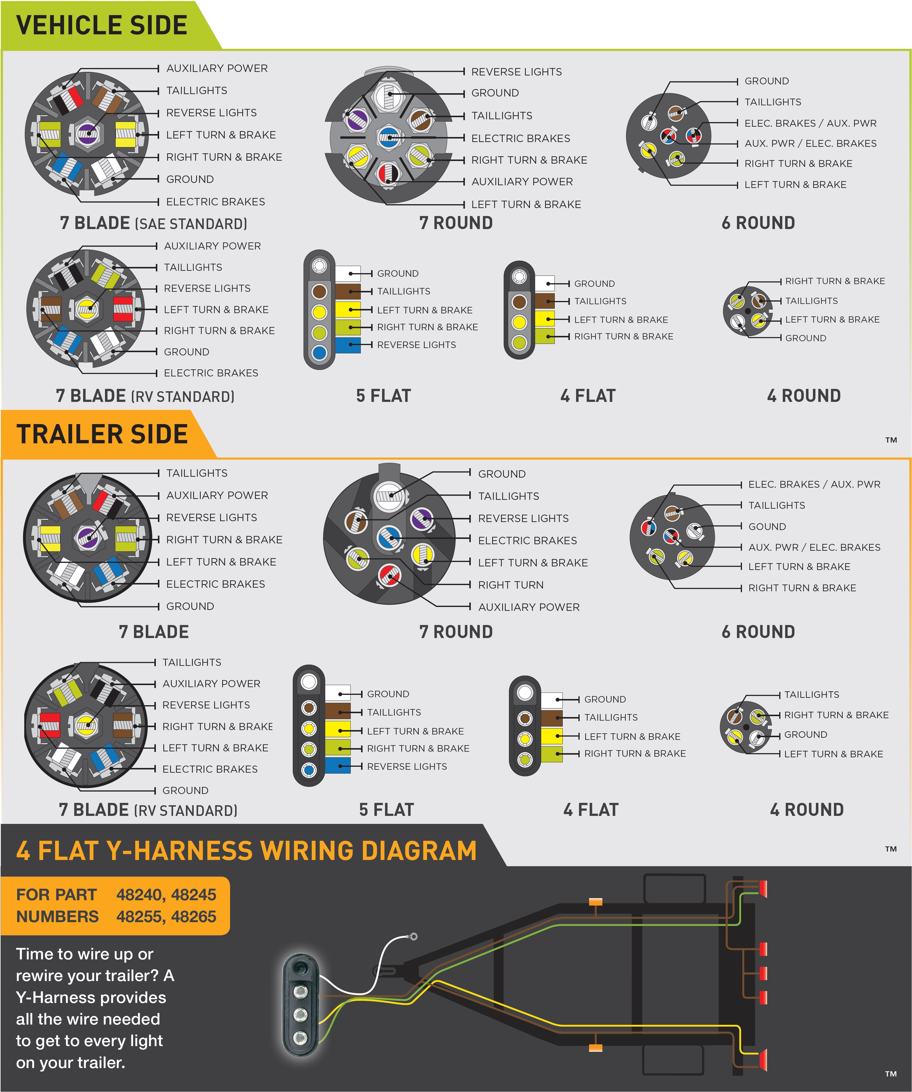
The Diagrams below show the Typical Trailer Wiring for 4 Pin Flat Connectors all the way to 7 Pin Round Connectors. It is Important to note that the "White Wire" is the ground wire, You will notice this even when you buy lights. A lot of LED Lights come with Black and White wires and people can easily confuse the black wire for the ground. A faulty and unsecured ground wire is often the.
7 Pin Trailer Plug Wiring Diagram Flat Wiring Diagram
5-Way Connectors 5-Way connectors are available allowing the basic hookup of the three lighting functions (running, turn, and brake) and, besides the ground, one pin is available to provide support for another function. Typically the 5-Way Flat is used for trailers with surge brakes or hydraulic brakes.
4 Pin Trailer Wiring Diagram 4 Pin Trailer Connector Wiring Diagram in 2020 Trailer
Blue: Reverse lockout What Size Wire Gauge is Used for a 5-Way Wiring Harness? The minimum suggested wire size for a 5-way trailer plug is 18 gauge for the turn, brake, running lights, and reverse lockout. The suggested minimum for the ground wire is 16 gauge. NOTE: *Some manufacturers will use red/black wires instead of brown/green/yellow.